basename: root name used for composing the name of the
image: ex: "object" will generate images called "objectNN" where "NN" is
the sequence number.If an image with that number already exists in disk,
then the old image WILL NOT be override; the new image will be renamed
basenameNN_i, where i=0 ... 20. After 20 consecutive images with the same
name (after basenameNN_20) an error will be returned
sequence number: this, together with the basename will
give the name of the resultant image. If you have this value in K, and
you are going to take a sequence of M images, then this value will be updated
automatically, and the images will be named "basenameK, basenameK+1 ....
basenameM
title: this will be the title of the image. This means
that this name will appear on the "OBJECT" keyword of the fits header,
and this name will appear, for example, when doing a "imhead <basenameMM>"
under iraf
Path: this must describe the complete path for the image
(filesystem and directory). If the directory does not exist, the system
will NOT create it, but will return an error saying that the directory
does not exist. The user will need to create it manually using "mkdir"
under UNIX or IRAF
comment: Any additional information desired. This will
appear on the image headers as a COMMENT keyword
exposure time: time, in seconds, that the detector will
be exposed to photons. This number is the TOTAL exposure time, which means
that the read time is included. The minimum exposure time is, therefore,
the readout time, currently aprox 3.5 seconds. If the user types in "10",
then the detector will be in a "idle" state (not clocking) only 6.5 seconds,
and the remaining time will be the readout time
fowler: number of fowler samples to take (number of times
the detector will be reset prior to the exposure and will be read after
the exposure).
coadds: number of coadds performed in memory before writing
the image to disk. There is no limit in this number.
Repeats: number of sequences to take. Every "sequence"
will result in an image, even when this image can be itself the result
of several reset-expose-read sequences coadded. See algorithm scheme above
observer: name of the observer. This will appear on the
fits header as a the value of the "OBSERVER" keyword
write automatically: If checked ,the image will be written
to disk automatically after being read and preprocessed. If not checked,
a button called "write" will appear when the image is ready for being written,
so the user can examine the image and write it only if desired
display automatically: If checked, the image will be
displayed, when ready, automatically on the image displayer (Ximtool or
DS9) if this is opened
All this is "static" information, in the sense that cannot be changed
while the actual image is in progress
GO: initiates everything.
ABORT: abort all activity immediately (whatever status
the system is) and return to the idle state. Current image will be lost
STOP sequence: will wait until the current image is taken,
and then stop gracefully
STOP coadd: will wait until the current coadd finish,
and then will stop gracefully.
The "looping" algorithm is:
DO sequence TIMES {
IF (STOP sequence)
EXIT
DO coadd TIMES {
IF (STOP coadd)
EXIT
DO fowler TIMES
reset
expose
DO fowler TIMES
read
subtract (exposed frame
- reset frame)
unscramble, write to disk
display (if selected)
}
}
Miscellaneous controls
QUIT: This button will close the GUI,
causing the disconnection to the controller, the filter wheel and the TCS
(if connected). A confirmation will be required
Select Plug-In: This is a
drop-down menu which allows to open any available Plug-In
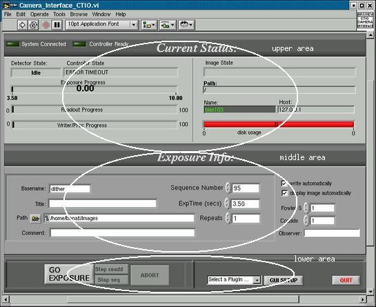
All the status returned is in the upper part of the GUI. The status
is:
System Connected light: When "on" indicates that the client
is connected with the Server (basically, the GUI is connected to the Software
which actually handles the system)
Controller Ready light: When "on" indicates that the
controller was successfully initialized and that it is ready for receiving
commands
If this two lights are "on" means that the system is totally ready. All this initialization process should take about 2-3 seconds
Left side: all the controller-related issues (reset, read, expose)
Controller State: upper part: messages related to the
status of the controller (like current task, information, etc.)
Detector State: state of the detector; this can be: idle
(doing nothing but in continuos reset mode)
resetting (in a reset cycle, clocking out the reset frame, prior to expose)
exposing (exposed to photons with no clocking)
reading (in a read cycle, clocking out the array the exposed frame)
Exposure Progress: exposure time progress, in seconds,
from minimum exp. time (readout time) to requested exposure time
Readout Progress: percentage of the frame read so far.
This bar will change with either the reset or the read cycles (in both
cases we are reading out the array)
Write Progress: Progress of the process of writing the
image to disk
Right Side: all the host-related issues (like image on disk, etc.):
Image State: what is the status of the writing or preprocessing
of the image on the host (like making the coadding, waiting for the next
frame to finish or writing the image)
Path: actual path to the image being processed (normally
the same specified for the user)
Name: actual name of the images being written (normally
the same specified for the user)
Disk Usage: usage of the current disk (filesystem). It
will turn red and return an error when the disk space remaining is not
enough for holding the requested images
Host: name or IP address of the machine in which the
images are being written