
|
Celebrating 75 Years of Discovery
|
|
Double Spectrograph (DBSP) Overview
View the original manual.
The Double Spectrograph (DBSP) is a low-to-medium resolution (R ~ 1,000 to 10,000) grating instrument for the Palomar 200-inch telescope Cassegrain focus that uses a dichroic (at, e.g., 5200 Å) to split light into separate red and blue channels ("sides"), observed simultaneously. In addition to 128″-long slits of various widths; slit segments that may be moved spatially by ± 26″.
The Overview describes the instrument, with some theory of operation, and presents some detailed information needed while planning a run (e.g., choice of dichroic and gratings; calculation of grating angles). The Cookbook describes, in a step-by-step fashion, how the instrument is operated during a run—particularly the requisite computer commands.
- News
- Experts
- Documentation
- Overview
- Introduction
- Optics
- Grating angle, spectral resolution
- Slit choices
- Dichroic curves
- Grating specs and curves
- Appendices
Contents
1. News
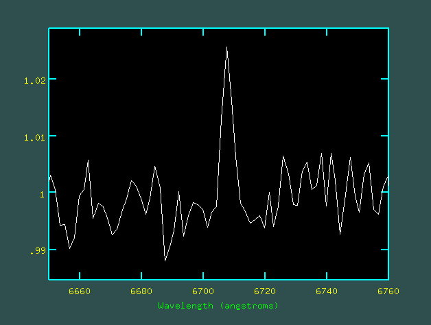
6708 Å emission line in 40 sec dome flat, 1.0″ slit. |
Dome Flats 2015 May 17 (C. Heffner)
An emission line near 6708 Å is sometimes present in dome flats taken with the high lamp. Note that when these flats are used in data reduction, it can create a spurious absorption line at that wavelength. A normalized plot of the emission line in a dome flat is shown to the right.
Red Upgrade 2011 December 18 (E. Kirby)
The CCD for the red channel has been replaced. On 27 October 2011, the old red detector (1024 × 1024, 24 µm pixels) was replaced with an LBNL deep-depletion CCD (4096 × 2048, 15 µm pixels).
This upgrade increased the red channel's throughput by a factor of 1.5 shortward of 8000 Å. Longward of 8000 Å, the throughput increased drastically, and you can expect excellent sensitivity up to and beyond 1 µm.
The longer detector also increased the spectral range of a single exposure by a factor of 2.5. However, the camera was not designed for such a large field, and the reddest 1000 pixels may have unacceptable optical quality. Please decide whether to use this section of the chip based on the requirements of your program.
This thick chip is an excellent detector of cosmic rays. It is recommended that you limit your exposure times to 20 minutes or less.
The pixels on the new detector are smaller. The new plate scale is 0.293″/pixel. You may wish to bin by 2 pixels in the spatial axis.
The dichroic filters have second-order light leaks which affect wavelengths longward of 9100 Å. For observations in this range, the use of the order-blocking filter RG610 is recommended.
2. DBSP Experts
A support astronomer will be present in the afternoon to help with instrument setup.
2.a. During the Run
General troubleshooting, telescope or instrument: From noon to 10pm, the support astronomers will be available to help you. After 10pm the telescope operator should be able to help, and is your first source of information and instrument support during the night.
Problems during daytime: At least one member of the day crew is generally around from early morning until late afternoon, and they will either help you with the problem or direct you to the appropriate contact person.
Reporting instrument problems: Comments on instrument performance and requests for maintenance or repairs are to be made ASAP via the "pink sheet", a.k.a. the "malfunction report," which is available in the data room (Palomar lingo for 200-inch control room) or in the monastery (dormitory) kitchen. The pink sheet forms are also available online at Palomar maintenance page. Ask a staff member for help in filling out a pink sheet.
After the problem is resolved, the observer will receive, for his/her records, the original pink sheet annotated with the corrective action taken. No response from the observer is required at that stage.
2.b. Pre-Run Planning, Instrument Information
Scheduling, logistics, and instrumentation: Palomar support team.
3. Documentation
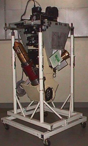
DBSP: a two-channel (Red/Blue), low- to medium-resolution grating spectrograph, seen here in its handling cart.
Raw spectra—vertical slit images in telluric lines, with bright knots from HH objects.

Raytrace of DBSP Red.
Most of what you need to prepare a proposal and make your instrument setup choices is in Overview.
Most of what you need to operate the instrument step-by-step at the telescope is in Cookbook.
The grating curves and catalog of comparison-lamp spectra found in reference 4 below, give a nice overview of the gratings and arc lamps available. However, the blue camera curves are obsolete due to the fact that the blue side camera has changed. The most useful resource is the online NOAO Spectral Atlas. This atlas is very useful for identifying arc lines in DBSP images given the parameters from the online calculator and/or the IRAF script grating calculator on the mountain.
- J.B. Oke & J.E. Gunn 1982, PASP, vol. 94, p. 586 — a journal paper describing the instrument shortly after it was built. Very good for mechanical and optical descriptions, which tend to remain current, but the CCD and computer control information is of course totally obsolete. Note that both cameras have been replaced.
- The Double Spectrograph, May 1997, by mph (Martha Haynes, at Cornell)—a concise (13-page), cookbook-style guide with particular attention to the details of computer control syntax (obsolete) and procedures for obtaining calibration spectra. This document can be found in the DBSP notebook in the 200-inch control room.
- 200-Inch Hale Telescope Cassegrain Spectrograph—1995, an update by Robert Brucato of Section V of the Palomar Observatory Manual; the original is cited immediately below. A 1/4-inch-thick document, most of which is totally out of date but there is a somewhat useful inclusion called:
- APPENDIX 5-B Atlas of arc lines for the Double Spectrograph, 1990, by Helen Johnston, Caltech (revised August 1991). This is a large collection of spectra taken on the internal "comparison" or (wavelength) calibration lamps. The spectra can be useful for a quick look reference, but the NOAO atlas is much more exact.
- APPENDIX 5-A Grating Angle vs. Wavelength is useful for a general overview of what's available while choosing a grating, but you should use the Grating Angle Calculator in the online manuals to find the grating angle that will give a desired central wavelength (don't just interpolate on the hardcopy plots—the other scientists will mock your technophobia, and you'll miss a lot of other useful numbers coughed up by the calculator). The grating curves here contain a conceptual error in failing to distinguish red and blue sides for all gratings: the two sides have different angles between collimator and camera beams, and so must have different grating curves—this will give errors of order 500 Å on the 1200 lines/mm gratings. Most of the rest of the information in this manual has been absorbed into the supported online documentation.
- Operation Instructions for the 5-Meter Hale Telescope Double Spectrograph—original (1983) version of Section V of the Palomar Observatory Manual, J. B. Oke (revised 7/29/85). Dated by now but of historical interest. Totally superceded by the supported online documentation.
- IRAF Manual. See the IRAF home page for complete IRAF documentation. A very few basic IRAF commands are included in the DBSP Cookbook.
4. Overview (before the run)
4.a. Introduction
This Overview gives a brief outline of the DBSP (double spectrograph) for the Palomar 200-inch telescope, including some of the theory of operation and information needed for advance planning of an observing run. For a step-by-step guide to operation at the telescope, go to the Cookbook.
A photo shows DBSP in its handling cart. Entrance slits are at the top, and gratings are at the bottom; the grating angle adjustment knob for the red side is visible at the center of the black circular region. The red camera and dewar are mounted on the left, while the blue camera is partially visible at the right.
4.b. Optics
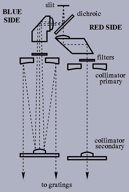
Fig. 1 from Oke and Gunn.

Diagram of one side, collimator and grating.
The diagram here (adapted from Oke & Gunn, PASP, vol. 94, p. 586, 1982) shows the light paths through the initial parts of the red- and blue-side optics. The slit lies in the f/15.7 Cassegrain focal plane of the Palomar 200-inch telescope. A dichroic splits the light into red and blue components; the observer chooses (once for each run) one of four dichroics, with dividing wavelengths of about 4800, 5200, 5500, or 6800 Å. (Transmission curves for the 5200 and 5500 Å dichroics are shown in the Dichroic section of this Overview).
The light then passes through field lenses, into prisms, and through filters before entering collimators through holes in the collimator primaries. (Filters may be changed by remote control during observations; a table of standard choices is given in the DBSP Cookbook, Hardware Setup section). The collimator secondaries are attached to (transparent) fused quartz plates that are optically flat.
From the collimators, the collimated red and blue beams proceed to the two gratings and then to the two cameras. The red camera currently consists of transmissive optics (lenses), while the blue side has a reflecting f/1.5 Schmidt camera with a field-flattening lens immediately in front of the detector. The second schematic shows the grating configuration and defines the angles relevant to wavelength calculations. The quantity directly set by dials on the side of the spectrograph is called the grating angle, and is the angle between the incident optical beam (from the collimator) and the normal to the grating.
4.c. Grating Angle, Spectral Resolution
The equation
a (sin θm − sin θi) = mλ
is used to solve for the grating angle to which a grating must be set to place the desired wavelength at the center of the CCD. An important point is that the sum of the grating angle and the angle made by the outgoing diffracted beam is fixed by the geometry of the instrument. For the red side, this sum is 35.00°; for the blue side, it is 38.50°.
NOTE: There is a grating calculator available.
The calculator is an IRAF script (by R. Burruss) resident on the workstation used for DBSP.
It is called dbangle and is located in the dbsp tasks. Use the web-based calculator to fill
out your green sheet, and use the IRAF script to fine tune your settings if necessary.
NOTE ON CENTERFIELD CAMERA: Currently, an Andor camera is used as a slit viewing camera. It views the reflective slit apertures and is used to accurately put objects onto the slit. This camera is sometimes called the DBSP centerfield camera. The Andor camera allows the user to save images of the field, and it is more sensitive than the older Xybion and Finger Lakes Instruments (FLI) cameras.
The old Xybion camera is an image intensified system. This camera has the advantage of being fast for brighter objects. The Xybion has the disadvantage of not being able to save images. The other alternative that is available is an FLI CCD. The advantage of the CCD is that you can save images of the field. The FLI camera was purchased with targets of opportunity in mind. The FLI has a filter wheel (g',i',r',ND,open) which can be used for Photometry. The fastest the FLI can update is about two seconds per image. Like the Xybion it can integrate for longer until the sky background is reached. The unvignetted field of view for all cameras is about 120″ × 70″.
The following is a calculator that will solve for the grating angle needed to put your desired wavelength onto the center of the CCD. This angle is a function of spectral order, choice of red or blue camera geometry, and grating lines/millimeter. All of the options are laid out in the calculator, or you may look at the table in section Grating Specs.
NOTE ON GRATING SELECTION: there is only one copy of each grating (with a given number of lines per mm and blaze angle), so you cannot, for example, put the 158 lines/mm one into both RED and BLUE sides. Any of the complement of 8 gratings may be put into either RED or BLUE sides, though.
To enable correction of mechanical offsets in the readout dials, blaze angle is requested to uniquely identify the grating. Blaze angle is not otherwise relevant to the grating angle calculation. Thanks to these empirical offsets [NYI], calculator accuracy is about 1′; due to their variation, answers for different gratings with the same lines/mm will vary by typically 10′. If this latter accuracy is OK, you could use any blaze angle; but it doesn't hurt to know what it is, either.
Also, the calculator will ask for slit width, which is used to compute the achieved spectral resolution, but not for the primary calculation of grating angle.
Grating angle = 0 puts the grating perpendicular to the incident beam from the collimator (the grating will be horizontal if the telescope is at zenith). To move to a positive angle, turn the dial counterclockwise (for both red and blue sides). This makes the grating turn its "face" toward the camera. The day crew or support astronomers will set the grating angle for you based on the value you entered on the "green sheet."
The focal length of the red camera is 12 inches, and the focal length of the blue camera is 9inches. The grating angle calculator above will give dispersion, resolution, spectral coverage, etc. for the wavelength of observation.
The dispersion is also presented in tabular form, go to section Grating Specs. The values there are representative, evaluated at the blaze wavelength, but dispersion is a very slow function of wavelength.
4.d. Slit Choices
5200 Å dichroic.
5500 Å dichroic.
The DBSP may be operated with a single long slit of length 128″, and available slit widths are 1/2, 1, 1.5, 2, 4, 6, 8 and 10″. These different slits are on a wheel allowing them to be changed quickly during observations.
4.e. Dichroic Curves
The observer may choose (in advance, on the setup Green Sheet) one of four dichroics that divide red and blue sides at roughly 4800, 5200, 5500, and 6800 Å. Curves for the middle two (5200 and 5500 Å) are given here. We have no curves for D48 or D68, but their quality is presumably comparable.
It is also possible to observe with no dichroic (giving maximum light into the red camera) or a mirror in place of the dichroic (giving maximum light into the blue camera, IF THE MIRROR COATING IS FRESH). These modes are not recommended, for the following reasons:
- The no-dichroic mode gives a non-standard optical pathlength into the red camera, and it may not be possible to achieve optimum focus—i.e., best spectral resolution.
- The mirror-in-place-of-dichroic has an old aluminum coating that has probably lost more blue reflectance than the D68 dichroic. If you are tempted to use the mirror to get best blue-side reflectance, use, e.g., the 6800 Å dichroic instead.
4.f. Grating Specs (lines/mm, blaze, dispersion); Grating Curves (wavelength vs. angle)
| Overview of Gratings | ||||
|---|---|---|---|---|
| lines/mm | 1st order blaze (Å) |
Useful range (Å) (to blaze 1/2-intensity) |
Red camera dispersion (Å/mm) |
Blue camera dispersion (Å/mm) |
| 158 [a] | 7560 | 5000 – 11300 | 201 1st [c] | 135 2nd [d] |
| 300 [b] | 3990 | 2700-6000 | – | 140 1st |
| 316 [a] | 7150 | 4800 – 10700 | 102 1st | – |
| 600 [b] | 3780 | 2500 – 5700 | – | 71 1st |
| 600 [a] | 9500 | 6300 – 14300 | 54 1st | – |
| 1200 [b] | 4700 | 3100 – 7100 | – | 36 1st |
| 1200 | 7100 | 4700 – 10700 | 27 1st | 36 1st |
| 1200 | 9400 | 6300 – 14100 | 26 1st | 35 1st |
| [a] silver coating, can be used only longward of 3500Å; [b] can be used only in blue spectrograph; [c] first order; [d] second order. | ||||
NOTE: there is only one copy of each of these gratings, so you cannot, e.g., put the 158 lines/mm one into both RED and BLUE sides. Any of the complement of 8 gratings can be put into either RED or BLUE sides, though. "Useful Range" gives the wavelength limits at which diffracted intensity drops to 1/2 of its peak value (2/3 and 3/2 of the blaze wavelength, by a common rule of thumb).
5. Appendices
5.a. Grating Installation (done by Palomar staff)
Requested gratings are installed by the day crew as part of instrument setup. Actual changes take roughly 10 minutes per side. Note that gratings can go in either side, but RED/BLUE grating rotators are not interchangeable.

Grating cell in drum (left), grating rotator (right).
- If you intend to replace the grating, find the empty drum into which it will go, and the drum with the new grating you want to install; these are stored in the cabinet near the door leading from the dome to the elevator area. Set the drum on the wooden desk nearby, and put out the Allen wrench with the large handle, too.
- Loosen the single lock-screw at bottom center of the grating rotator.
- Move the grating angle to 0 degrees and retighten the lock-screw.
- Loosen the 4 symmetrically-placed screws holding the grating rotator in place (they are captured, so can't fall out). The 4 screws have black knobs, and are the outermost four in the right-hand diagram below.
- Holding the two handles, gently slide the rotator and attached grating out, toward you (careful, they are quite heavy—beginners use two hands).
- If it's the one you want, slide the grating back in and retighten screws; otherwise, carry it down the ladder from the Cass cage and put it in the drum on the wooden desk, then secure it with the four lip clamps.
- Use the Allen wrench with the round handle to loosen the screw in the center of the black knob on the grating rotator; when the rotator is free, put it on the replacement grating and tighten.
- Take the reloaded rotator back up to DBSP and reattach.
5.b. Setting Grating Angles
To find the correct grating angle for your setup and desired center wavelength, click on:
Calculator caveat: the resolving power returned by the calculator uses resolution per pixel, not per slitwidth like the other quantities given (hence this resolving power does not change with slit choice).
Refer to the right-hand side of the figure immediately above, showing a grating rotator as it would look when installed on the spectrometer:
- Recall that grating angle = 0 corresponds to having the face of the grating perpendicular to the beam incident from the collimator (grating face horizontal with telescope at zenith).
- Recall that increasing the grating angle involves tipping it toward the camera projecting out of the instrument at an odd angle—this is the counterclockwise direction for both blue and red sides.
- Release the clamp at bottom center.
- Set the angle by turning the black 8-pointed knob, and read the grating angle on the vernier scale viewed through the round magnifier—you can move the magnifier left and right if you first push down on the spring-loaded bar on which it is mounted.
- To read the vernier: see where the zero line on the fixed outer circle, at top, points on the scale on the inner circle, which is marked to the half-degree; to determine the number of arc minutes above (or below) that nearest half-degree, look to the right (or left) and take the number on the outer circle that lines up with any line on the inner circle (standard vernier procedure); to the right is 0 – 30 minutes and to the left is 31 – 59 minutes. The left read is confusing because you are subtracting from the next full degree. For example, say you have to set the vernier to 24 degrees 45 minutes. Set the zero line to 25 degrees and the slowly adjust the zero line to the left until any inner circle line matches up with 15 minutes "left". You are now at 24 degrees 45 minutes, because you subtracted 15 minutes from 25 degrees. Ask for help, it will make much more sense when you actually do it with supervision.
- Tighten the clamp while holding the knob steady (or it will move).
Questions? We've answered many common observing and operations questions in our observer FAQ page.
Please share your feedback on this page or any other Palomar topic at the
COO Feedback portal.
DBSP Overview / v 2.2.5
Last updated: 18 September 2020 ACM/CMH
|
|
|