You are ready to start the LFC program. Make sure you are in one the of 4 proper data disks:
Do NOT use /scr6 (reserved for the home directory and system files)
Do a df -k to determine which of the disks are free for use. Note that you have write permission in any of the /scr#/lfc directories, but you do NOT have write permission one level higher in any of the /scr# directories. Delete old data if necessary, and then create a new subdirectory for your data.
Start-up Sequence
Now enter the following commands in this order to start the LFC program (the order is crucial):- oasis% mcdcom This starts the LFC program. Once started, mcdcom will start
writing
data into the
current directory. Mcdcom recognizes the Unix commands ls and cd, and will write to any new
directory that you
point to. You can issue any other Unix command with the standard ! escape.
- ccd.001> mosaic <mode> This downloads the appropriate code to the DSP
controller and configures
mcdcom. The mode sets the clocking parameters. Currently, there are 5 modes:
- mosaic lfc2 This will setup Mcdcom to readout the
entire mosaic, binned 1 x 1.
- mosaic lfc2bin This will setup Mcdcom to readout
the
entire mosaic, binned 2 x 2.
- mosaic lfcfour This will setup Mcdcom to readout
the
central four chips, binned 1 x 1.
- mosaic lfczero This will setup Mcdcom to readout
only chip 0, binned 1 x 1.
- mosaic lfczerobin This will setup Mcdcom to readout
only chip 0, binned 2 x 2.
- mosaic lfcfind This will setup Mcdcom to readout
only chip 0, binned 2 x 2; useful for a quick find exposure.
The Binning Value and Raster Value parameters can be changed should the above options not meet your needs (the chip numbers readout cannot be changed). Seek assistance if you want to do this. For more information, see the mosaic command.
- mosaic lfc2 This will setup Mcdcom to readout the
entire mosaic, binned 1 x 1.
- ccd.001> shutter startup This initializes the shutter
- ccd.001> shutter home This sends the shutter to the home position
- ccd.001> filter home This homes the filter wheel; make sure estoff = 0!
- ccd.001> utility stat This displays and tests the current status of the utility
board
If shutter, filter, or utility commands report an error, quit mcdcom and retry this sequence. If you get the error again, try a cold boot or seek help
- ccd.001> fp <prefix> This sets the file prefix value. The default is
ccd. (note that you
need to specify the dot (".") if you want one to separate the prefix and the frame number)
- example fp lfc.
- lfc.001> fn <#> This sets the frame number. The default is 1
- lfc.001> fs <#> This sets the frame suffix. The iraf command
now appends .fits when it is toggled ON, and it removes the .fits when it is toggled OFF.
- example fn 101
- example fs .fits
- lfc.101.fits> You should now be ready to take data. Note that charge accumulates on
the chips during the startup procedure. The only way to fully remove this charge is to readout the chips with
either rm or a 0 second bias
exposure. Exposures are written in the format prefix###.chip, so the first exposure from this example would
produce six 17 Megabyte FITS files:
lfc.101.0 lfc.101.1 lfc.101.2 lfc.101.3 lfc.101.4 lfc.101.5
- lfc.102> You should now be more than ready to fill up some disks. Note that
your
prompt has
changed to the next exposure's filename.
Logsheets
Logsheets can be printed from planetx using:
planetx:/home/user> lpr logsheet5.ps Prints 5 logsheets
As of May 2006, there is an icon on planetx's right hand monitor called Print 5 LFC Logsheets. I'm not sure why, but some people like to delete icons.
View Postscript Logsheet
Camera Characteristics
Filter wheel has slots for 4 filters
6.1 inches square
Thickness: ~3 mm (min); 10 mm (max), but < 6 mm preferred due to weight considerations.
Contact: P200 Support about non-observatory filter mounting. Also see Rob Simcoe's LFC Page for more information.
Ccds
The six LFC ccds are SITe SI-002 chips, 2048 wide by 4096 pixels tall. Each pixel is 15 microns square, which corresponds to ~ 0.18" / pixel (0.175" / pixel at the center of the mosaic; 0.185" / pixel at the field edge).
1 - Largest DN value that still lies within 0.1% of the Integral Nonlinearity value.ccd # Bias
(DN)Gain
(e-/DN)Read Noise (e-) Saturation
(DN) 1Linearity Curves Normalized Linearity 0 650 2.0 11 59100 jpeg, postscript mean, time 1 1700 1.9 9 53400 jpeg, postscript mean, time 2 1100 2.1 9 40800 jpeg, postscript mean, time 3 2600 2.0 8 44000 jpeg, postscript mean, time 4 1700 2.1 8 21700 jpeg, postscript mean, time 5 4100 1.8 6 61400 jpeg, postscript mean, time
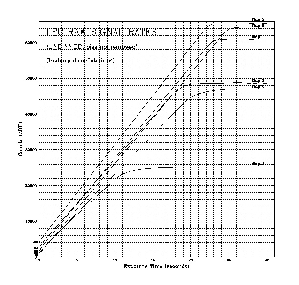
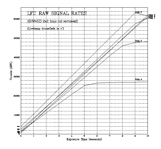
The ccds collect light at slightly different rates (gain). We've plotted the linearity curves together to create a tool to help you guage this rate difference. This can be useful if you want to keep the raw, unbiased chip4 below 21000 DN while displaying other chips.
Unbinned Raw Signal Rates (jpg, postscript)
Binned (2x2) Raw Signal Rates (jpg, postscript)
There are five LFC mosaic configurations (modes) that you can use. The lfc2 mode, using all 6 chips, is the default mode setup by the daycrew before you arrive. If you want to change this mode or build a custom mode, see the mosaic section of the Commands manual.
The binned modes (2x2; ~ 0.36" / pixel) have been tested on sky, and they appear to work very well. In fact, the wavy patterns in the bias frames disappear in binned mode. The readout is faster (56 seconds instead of 115 seconds) and the image file sizes are smaller (4.3 Mb instead of 17 Mb). The seeing at Palomar is typically ~ 1.0 to 1.5 arcseconds FWHM, sometimes as good as 0.8 to 0.9 arcseconds. In the binned mode, this would correspond to ~ 2 pixels per seeing disk in the very best conditions and ~ 3 - 4 pixels per seeing disk in the average Palomar conditions.
Mode (mosaic command) Chip Numbers Used Binning Value Raster Value Field Size Readout/Write Time lfc / lfc2 0, 1, 2, 3, 4, 5 1 x 1 No Raster 25.3' x 24.8' 115 seconds lfc2bin 0, 1, 2, 3, 4, 5 2 x 2 No Raster 25.3' x 24.8' 56 seconds lfcfour 0, 1, 2, 3 (central 4) 1 x 1 No Raster 12.5' x 24.8' 111 seconds lfczero 0 (chip 0) 1 x 1 No Raster 6' x 12.3' 105 seconds lfczerobin 0 (chip 0) 2 x 2 No Raster 6' x 12.3' 45 seconds lfcfind 0 (chip 0) 2 x 2 [0-1024 x 1024-2048] 6' x 6' 31 seconds
Dewar
The LFC dewar is large enough to hold LN2 for over 24 hours. The daycrew typically fills the dewar once during the day.
Dry nitrogen is continuously blown across the LFC dewar window at 5 PSI. If the weather is very humid you may want to ask the daycrew for more (~10 PSI). If condensation starts to form on the entrance window, you will see dark blobs grow near the center of the LFC field (upper left of chip 0, upper right of chip2...).
Filters
LFC Filter Specs
Filter Central 
(A)Width
(A)Thickness
(mm)Focus Offset
(mm from r')Domeflats * Transmission Text File r' 6255 1470 3.05 - 5 r'.txt i' 7680 1540 3.05 - 3 i'.txt z' ~9000 ~1800 (w/qe) 3.05 - 5 z'.txt g' 4660 1400 8.02 +1.5 40 g'.txt u' 3540 590 8.38 +1.6 120 (HIGHLAMP) u'.txt Rs 6930 1220 10.26 +2.0 8 Rs.txt Is 8190 1670 10.26 +2.0 5 Is.txt B-bess 4400 1000 7.0 +1.3 2 (HIGHLAMP) B.txt V-bess 5500 900 7.0 +1.3 40 V.txt R-bess 6300 1200 7.0 +1.3 10 R.txt I-bess 9000 3000 7.0 +1.3 I.txt Broad-RI 7670 2940 6.0 RI.txt H-alpha 6570 100 11.68 +2.8 120 see plots below S-II 6730 90 11.68 +2.8 120 see plots below 6610/100 6610 100 7.06 +1.3 120 see plots below 6650/100 6650 100 7.06 +1.3 120 see plots below 6700/100 6700 100 6.93 +1.3 120 see plots below 3990 3990 ? 7.67 +1.4 100(highlamp) not yet on record 4010/90 4010 90 12.19 +2.9? not yet on record 5200/70 5200 70 4.90 ? not yet on record 5085/70 5085 70 5.13 ? not yet on record
* Seconds to 10,000 DN(unbinned)
Figure: Sloan filters convolved with ccd quantum efficiency
u'.txt g'.txt r'.txt i'.txt z'.txt
Rs transmission curve (without Q.E.) Rs.txt
Is transmission curve (without Q.E.) Is.txt
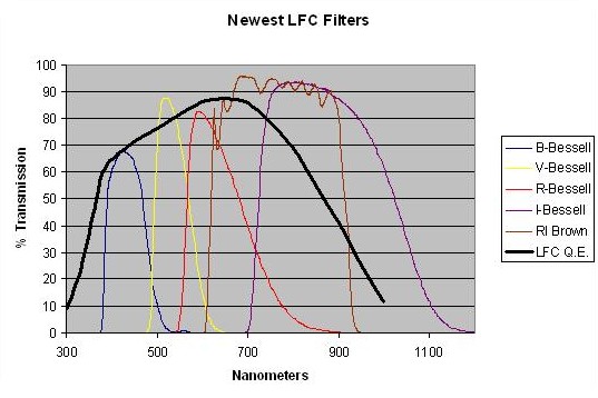
Figure: Newest (2006) LFC Bessell and custom RI filters
B-Bessell.txt
V-Bessell.txt
R-Bessell.txt
I-Bessell.txt
RI-Mike Brown.txt Rs transmission curve (without Q.E.)
Is transmission curve (without Q.E.)
New (Nov. 2007) Narrow Band Filters, Courtesy of Karl Stapelfeldt.
H-alpha transmission curve (without Q.E.)
S-II transmission curve (without Q.E.)
Custom LFC Filters
LFC Array Focus Maps
3mm Filter Map
8mm Filter Map
10mm Filter Map
Shutter
The shutter is comprised of two large rectangular blades. While one moves away from the field to start an exposure, the other moves over the field in the same direction to end an exposure, thus providing uniform illumination. The shutter will NOT go faster than 0.6 seconds. You will receive all sorts of trouble if you try to go faster than 0.6 seconds. The shutter is very stable at and above 0.6 seconds. The linearity curves show that the chips are very linear all the way down to 0.6 seconds.
There is no light leak around the shutter, you can take bias frames during the day if you want.
Calibration Images
- lfc.102> bias 0 bias This tells Mcdcom to prepare to take a bias exposure for
0 seconds and name it bias.
- lfc.102> go This starts the exposure.
- lfc.103> go 5
- lfc.103> dark 600 dark This tells Mcdcom to prepare to take a dark exposure for
600 seconds and name it dark.
- lfc.103> go This starts the exposure.
- lfc.108> tel lowlamp Turn on the lowlamp
- lfc.108> flat 5 domeflat-z This tells Mcdcom to prepare to take a flat exposure for
5 seconds and name it domeflat-z.
- lfc.108> go This starts the exposure.
- lfc.109> go 4
Bias Frames
When you are ready to take your first exposure, take a bias frame to clear all of the charge off of the chips. Charge will accumulate on the mosaic during the start-up procedure. The clear command will not remove this charge, no matter how many times you try to use it (caveat: I haven't tried more than 100 clear commands in a row. Feel free....).
This first exposure will likely show residual charge on the chips, you can throw them away if you want. The next exposures will be fine. To take 5 bias frames in a row, type:
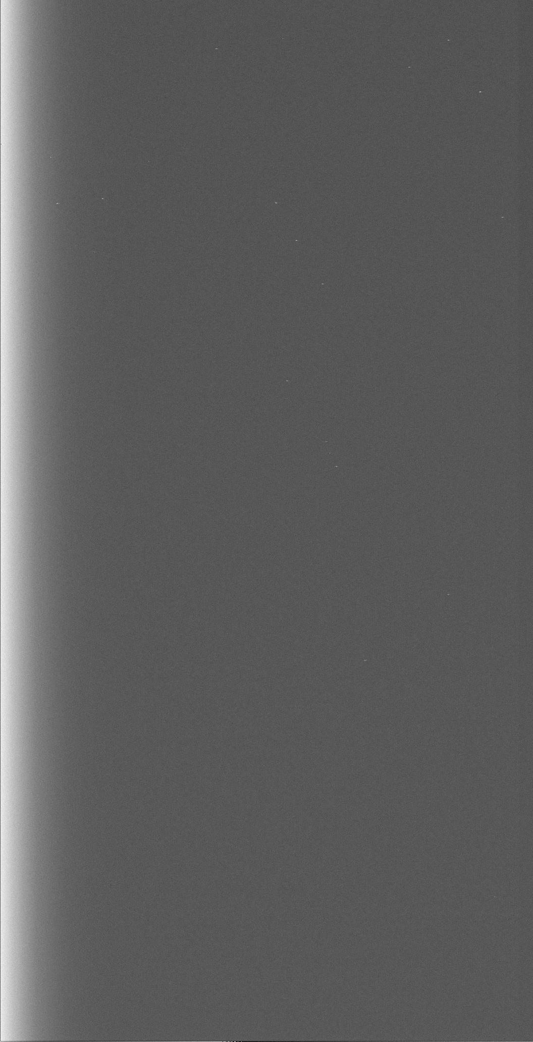
Your bias frame should look like this:
Dark Frames
As with most modern CCDs, there is no appreciable dark current in these chips. You can prove this for yourself with:
You'll find some hot pixels, some hot columns, and nothing to be alarmed about.
Dome Flats
Once the dome is dark (~ 4:00 PM), have someone open the mirror cover and make sure all of the dome lights are off. All domeflats are done with the telescope pointed up at the white part of the dome slits (no need to move the telescope). If you want to take u' domeflats, you will need to use the highlamp.
See Filters for exposure times.
To take 4 domeflats in a row, type:
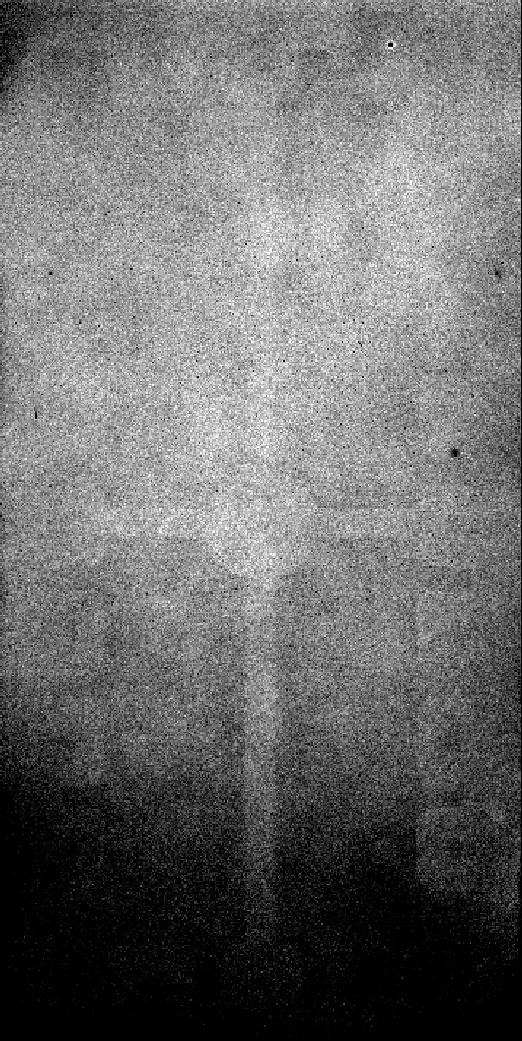
Your domeflat should look like this:
Sky Flats
Since the LFC has a light tight shutter (unlike COSMIC), you can take good skyflats. Note the LFC command istat gives you a quick one-line text output of the mean value of chip 0. This can be useful to check your sky level without having to take the time to display an image.
Defects / Features
The left sides of the ccds (column 1 to about column 75) are ~ 30 to 100 counts "hotter" than the rest of the chip. This is in the bias, and subtracts out nicely.
The field of view is unvignetted from the center of the mosaic to a circle about 22' out from the center. From this circle and continuing out to the field edge (22' to ~ 25') the field is up to 10% vignetted by the Wynne corrector lens. You will see the vignetting pattern at the outer edge of each chip, especially chips 4 and 5.
Look out for condensation "blobs" that might appear near the center of the mosaic field when the humidity gets very high. If this happens to you, have somebody check that the dry nitrogen is flowing over the dewar window. If it is, the dry nitrogen flow should be turned up.
Each chip has a few bad columns and a few small dead spots. Chip 4 has two bad columns down the center of the chip. Chip3 has small, in-focus "marks" (dare I say, "spooges") all over the ccd (need light to see them and you have to look close). These are defects on the surface of the ccd, and they will flatten out.
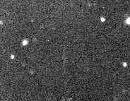
The 6 ccds are wired together in pairs to one of three controller boards. As a result, if something saturates (star, background) on one chip you will see a "ghost" of the saturation on the chip that shares the board. The ghost is usually tens of counts, which you can remove later through filter processing. In the image below, the core of a bright star saturated on chip 0 during a long exposure, which led to "bloom" trails. The pixels that actually saturated show up in the same location on chip 1, seen here:
Displaying Your Images
You can use Ximtool as a stand-alone to display your images. If you want to use iraf you need to append a .fits to each image filename to keep iraf happy. And note that the images that LFC writes are unsigned integers; iraf wants to display signed integers by default.
You can use the IRAF toggle to scale the output image data to iraf friendly signed integer values. Here's the original ccdcom explanation (this was verified to work on LFC images in February 2005):
- lfc.113> iraf
IRAF (among others) is finicky about dealing with 16-bit FITS
images, but the dynamic range and A/D converters for our CCDs are such
that we want to save all 16 bits.  The "iraf" option causes
ccdcom to scale all FITS images to pack 16-bits of unsigned data
(so-called "ushort") into standard FITS signed 16-bit integers
("short" or BITPIX=16 FITS format).

Specifically, this the FITS header parameter BZERO is set to 32768, and
the image is written as a FITS-standard 16-bit integer data file.  IRAF
et al. use the value of BZERO in the FITS header to restore the pixel
values to those provided by the camera.

By contrast, the old "not IRAF" format images stored pixel data as
unsigned 16-bit integers, resulting in a non-standard FITS format image
(a "ushort" image in IRAF parlance) that most FITS readers cannot read
without special handling.
To start an iraf session from planetx, click on the icon called LFC iraf or type start_LFC_iraf in a Terminal window. The path out of planetx to oasis is /lfc.
Pointing
You should check the pointing at the start of your first night, especially if a previous observer used a different instrument. Have the telescope operator point to a 5th or 6th magnitude star and take a 1 second exposure:
- lfc.113> obj 1 point This tells Mcdcom to prepare to take an exposure for
1 second and name it point.
- lfc.113> go This starts the exposure.
The star should be somewhere near the center of the field, so display chip 0 first and look at the top left of the chip. A 5th magnitude star is bright enough that you should see the reflection somewhere on chip 0, if it isn't totally there already. If the pointing is good, the star might be behind the 15 arcsecond gaps at the center. Change the low - high display values to see the core of the star, and then move the telescope as appropriate to set the pointing wherever you want. You may need to display another chip in order to see the star.
Take another exposure to verify that you put the star in the right spot. When you are happy, have the night assistant "X" the pointing, which sets the telescope's pointing model to its current position. The pointing should now be good for the rest of your run.
Focus
During the winter season, you will likely find focus values from 31.00 to 34.00 millimeters. In summer, you may find focus values from 28.00 to 31.00 millimeters. The Sloan r', i', and z' filters are parfocal. The Sloan g' and u' filters are 1.5 to 1.7 millimeters higher.
Note that due to the curvature of the field at the 6 ccds in the focal plane, the best place to inspect focus stars is about 1/3 out from the center of the mosaic. This will provide the best focus distribution over the entire field. Note the following LFC Array Focus Maps:
3mm Filter Map
8mm Filter Map
10mm Filter Map
Run the focus_fine and focus_coarse scripts to focus the telescope. View this help file for instructions on how to use the focus scripts.
Image / Seeing Analysis
You can measure the seeing and do some simple statistics with the iraf command imexamine. Put the cursor over a star and hit the r key. A radial plot should appear with three numbers in the lower right corner of the window. The middle number is a good approximation of the profile fit in pixels. In unbinned mode, a pixel is 0.18". In binned mode, a pixel is 0.36".
The primary mirror is astigmatic. Use this to your advantage. With the cursor over a star, hit the e key and look at the contour plot. When the telescope focus is a little too low, you will see that stars are elongated either left to right, or up and down. When the telescope focus is a little too high, the axis flips. When the telescope focus is just right, the star will be round. As you inspect stars in your science field later in the night, you can use this information to bump focus a little as stars start to elongate one way or the other.
If the seeing is bad, say greater than 2.0", all bets are off; everything is round.
Science Exposures
Here are some examples of what you might do when taking normal exposures:
- lfc.115> object 300 target1_zprime This sets up mcdcom to take a 300 second exposure and name the
FITS header target1_zprime
- lfc.115> go This starts the exposure
- lfc.116> telescope offset 15 15 This moves (dithers) the telescope 15" EAST and 15" NORTH
- lfc.116> et 500 This increases the exposure time to 500 seconds while keeping you in object
mode and
leaving the name as target1_zprime
- lfc.116> go
- lfc.117> telescope goffset -15 -30 This moves the telescope AND the guider box
(guided offset, note the g) 15" WEST and 30" SOUTH
- lfc.117> telescope focbump 1.5 This increases the telescope focus by 1.5 millimeters
- lfc.117> filter move 1 This moves the filter wheel to position number 1
- lfc.117> object 600 target1_gprime This sets the exposure time to 600 seconds and names it
target1_gprime
- lfc.117> go
To see the full list of mcdcom commands, see the LFC Commands section.
Guiding
Most of the guider information can be learned from the guider's HELP window invoked by the HELP menu option on the GUI (view this help file).
To start the guider, click the icon labeled start_lfcguide located on the planetx desktop.
The LFC guider is a SITe 512 x 512 ccd with 0.54" pixels, corresponding to a field size of 138" x 138". This ccd is located in the southeast corner of the mosaic next to LFC chips 3 and 5 at the outer edge of the field. Since it is in the cooled focal plane (which means that it is behind your filter AND the shutter), the guider is very sensitive to faint stars. Two important points:
- When you are in good focus, the guider should be in focus too (although the image quality is not as nice at the outer edge
of the LFC field).
- The shutter needs to be OPEN in order for the guider ccd to see anything.
A typical exposure and guiding sequence:
- Start your science exposure.
- Make sure the exposure slider is set to a reasonable value, like 10 seconds. This slider controls the integration time that the
guider ccd uses before displaying the first image (when set to 0.0 seconds, the guider reads out as fast as
it can which is 0.7 seconds).
- Once the guider displays its first image, look for a guide star. Change the display gray scale if necessary by holding the right
button down and moving the mouse around in the guide display field. If you don't see anything, increase the guider exposure time.
- Grab and move both the sky box and the signal box over a star (don't need to be centered).
- Press START. If the guide box detects the star it will turn yellow which means the next frame will start guiding. A green
box means it is guiding happily.
- The good news is the telescope tracks like a champ for up to 300 seconds. If you're not happy with this method, you can use the
find command to open the shutter and send the guider images to the GUI. This way you can locate a guide star, quit the find
routine with ^C, and then start your exposure. Note that find opens the shutter exposing the science chips to the sky too. Nobody ever uses this method. But feel free...
- Start your science exposure.
The strip charts are nice tools to help you gauge seeing and sky transparency.
The display scales automatically by default. If you don't like this, uncheck the Auto Scale button. The background level is determined from the sky box, so if a bright star is in the field, you may not like the autoscale.
Dithering / Telescope Commands
The guider provides communication between the LFC and the telescope. The guider must be running for the following telescope commands to work:
- lfc.118> telescope focbump <dfocus> Move the current telescope focus by the
amount
dfocus in
millimeters. Positive value moves focus out, negative value moves focus in.
- lfc.118> telescope focgo <focusmm> Move the current telescope focus to the
absolute
position
focusmm in millimeters.
- lfc.118> telescope goffset <dra" ddec"> Move (dither) the telescope AND the
guider
box in arcseconds
for both right ascension and declination. Positive values move the telescope and guider box east and north
respectively.
Negative values move the telescope and guider box west and south respectively. Note that your guide field
is
about two arcminutes
across. Take care to keep your guide star within the guider field.
- lfc.118> telescope offset <dra" ddec"> Move (dither) the telescope in arcseconds
for
both right
ascension and declination. Positive values move the telescope east and north respectively. Negative
values
move the telescope
west and south respectively. Note that you are NOT moving the guide box with this command.
- lfc.118> telescope highlamp Turn on the highlamp
- lfc.118> telescope lowlamp Turn on the lowlamp
- lfc.118> telescope arclamp Turn on the arclamp
- lfc.118> telescope lampsoff Turn off the lamps
For a full list of telescope commands, see the Telescope Commands section.
Scripts
There are several scripts available in the oasis /scr6/home/lfc/scripts directory that you can copy to your data directory to use (and edit, once copied). Look at the scripts. You will notice how easy it is to write your own, perhaps to setup an observing dither pattern, etc.
To run a script, type source <script>.
- dither5, dither9 These scripts will run a series of exposures (5 steps or 9 steps) using a boxed dither
pattern starting with a guide star located at the center of the guide field. The best way to implement one of these dither
scripts is to take a normal, guided science exposure using a guide star anywhere in the guider field. When the exposure is done,
move the telescope to put the guide star in the center of the guider field and then run the script:
- After starting a normal exposure, say you select a guide star that is 20" east and 30" south from the center of the guider
field. The guider field of view is about 90 arcseconds across. When this exposure is complete:
- lfc.118> tel goffset 20 -30
- lfc.118> source dither9
- After starting a normal exposure, say you select a guide star that is 20" east and 30" south from the center of the guider
field. The guider field of view is about 90 arcseconds across. When this exposure is complete:
- doflats Without editing, this script assumes that you are in reasonably good focus.
It takes 5 filter
position 1 dome flats, followed by 5 filter position 2, 5 filter position 3, and 5
filter position 4 dome
flats. After copying to your working directory, edit the script to suit your needs (your position # filter name will likely be
different).
- lfc.118> source doflats
- focus_fine Without editing, this script takes a 5 second exposure, increments the telescope
by 0.1 millimeters, and moves the
telescope. After the first exposure, the telescope is moved 15 arcseconds north. Six more exposures are
taken, followed by 7 arcsecond north
telescope moves. If you would like to change the exposure time you may do so by editing the first line of the focus scripts, focus (N) focus_fine. Rm is used at the end of the script to readout the mosaic. Obj 5 is the last
line, intended to get you back into
normal exposure mode lest you forget that you are in the no-read focus mode. After copying to your working
directory, edit this script to suit
your needs.
The two best variations of focusplate are focus_coarse and focus_fine. We have also added a .5 mm increment focus script for the first night of a run focus_first.
Note the ! sleep # lines. Make sure you wait long enough before executing the next command, especially if you increase the size of telescope moves or focus changes.
- lfc.118> source focusplate
- standard4 Without editing, this script takes two dithered exposures of a standard
star or field in each of the four
central chips. You should be near the center of the mosaic when you start the script; the telescope will move
120 arcseconds north and 120
arcseconds east to start; then return each time before moving off to the next ccd. After copying to your working directory,
edit this script to suit your
needs. There should be a standard6 script that incorporates all 6 chips now too.
Note the ! sleep # lines. Make sure you wait long enough before executing the next command, especially if you increase the size of telescope moves or focus changes.
- lfc.118> source standard4
- tarem, todat-lfc These scripts work together to create a single tar file for each image
frameset. Look at todat-lfc for more information.
Trouble Shooter
The most common problem with the LFC is a "hung" utility board. The utility board controls the shutter and the filter wheel. When it hangs, you won't be able to move the filter wheel or take an exposure. Usually, a scary "Timed-out" error message appears several times in the mcdcom window if you try to do something when the board has hung. At other times, the failure may be subtle. If you suspect trouble, look at the output from the utility stat command. At the left of the output, you should see a list of voltages (+40, +15, -15, +5) followed by the actual voltage value. If these actual values are zero (or some outrageous number), then the utility board is likely hosed. If you think the utility board has gone bad, do a cold boot. The utility board hangs about once or twice every 2 - 3 nights.
Sometimes, the filter wheel will fail to converge to the proper position after a move request, and a warning "filter wheel didn't make it into fine lock" will result. If this happens, just issue the filter move # command again until the filter wheel has seated properly. Pay attention to the estoff= value. This value should be 0 before you take an exposure.
For a full list of LFC troubleshooting errors, go to Rob Simcoe's LFC Troubleshooter Web Page
Data Backup
The tape drives are located next to oasis in the computer room on the mezzanine floor (next to the E-lab). Your taping options are:- Eliant 8500 type 8mm Helical Scan tape drive (device number 0)
- tar cvf /dev/rmt/0cbn lfc.*
We can typically get 7 Gb on a 112M Exabyte tape (5Gb native : 10Gb compressed) using compressed mode, so that's about a 1:1.4 compression of LFC images. A 160M tape (7Gb native : 14Gb compressed) should hold about 10 Gb.
- Sony 4mm DAT DDS3 tape drive (device number 2)
- tar cvf /dev/rmt/2cbn lfc.*
A 125M tape will hold 12Gb native and 24Gb compressed, but we haven't tested this.
- There are two fast PCs in the data room (planetx and vulcan) with DVD burners. See the mountain staff for help.
End Of The Night
Nothing special needs to be done at the end of the night. The dewar should still have plenty of Ln2, and the daycrew will fill it in the afternoon.
When your last night is over, please try to have your taping done before the next observer arrives in the afternoon. With the limited disk space on oasis, your data can't be guaranteed to remain on disk after you leave. Contact the mountain staff and the next observer if you need to make special arrangements.
Tables
LFC Array Focus Maps
3mm Filter Map
8mm Filter Map
10mm Filter Map
Ccds
1 - Largest DN value that still lies within 0.1% of the Integral Nonlinearity value.ccd # Bias
(DN)Gain
(e-/DN)Read Noise (e-) Saturation
(DN) 1Linearity Curves Normalized Linearity 0 650 2.0 11 59100 jpeg, postscript mean, time 1 1700 1.9 9 53400 jpeg, postscript mean, time 2 1100 2.1 9 40800 jpeg, postscript mean, time 3 2600 2.0 8 44000 jpeg, postscript mean, time 4 1700 2.1 8 21700 jpeg, postscript mean, time 5 4100 1.8 6 61400 jpeg, postscript mean, time
Mosaic
Mode (mosaic command) Chip Numbers Used Binning Value Raster Value Field Size Readout/Write Time lfc / lfc2 0, 1, 2, 3, 4, 5 1 x 1 No Raster 25.3' x 24.8' 115 seconds lfc2bin 0, 1, 2, 3, 4, 5 2 x 2 No Raster 25.3' x 24.8' 56 seconds lfcfour 0, 1, 2, 3 (central 4) 1 x 1 No Raster 12.5' x 24.8' 111 seconds lfczero 0 (chip 0) 1 x 1 No Raster 6' x 12.3' 105 seconds lfczerobin 0 (chip 0) 2 x 2 No Raster 6' x 12.3' 45 seconds lfcfind 0 (chip 0) 2 x 2 [0-1024 x 1024-2048] 6' x 6' 31 seconds
Filters
Filter Central
(A)Width
(A)Thickness
(mm)Focus Offset
(mm from r')Domeflats * Dark Sky Level *
(raw chip 0)r' 6255 1470 3.05 - 5 1400 i' 7680 1540 3.05 - 3 650 z' ~9000 ~1800 (w/qe) 3.05 - 5 750 g' 4660 1400 8.02 +1.5 40 u' 3540 590 8.38 +1.6 120 (HIGHLAMP) Rs 6930 1220 10.26 +2.0 3 Is 8190 1670 10.26 +2.0 3 B-bess 4400 1000 7.0 +1.3 3 V-bess 5500 900 7.0 +1.3 3 R-bess 6300 1200 7.0 +1.3 3 I-bess 9000 3000 7.0 +1.3 3 Broad-RI 7670 2940 6.0
* Seconds to 10,000 DN (unbinned)
