The filter list file is an ascii file describing the names, IDs, focus,
position and color code representation for each installed filter. The layout
of the file is:
[wheel 1 name]
filtername1="ID1 position focus colorcode"
filtername2 = ...
..
[wheel 2 name]
.
.
This is the file read when for displaying the filter names and defining the positions on the GUI. The operator who install the filters can edit this file manually or can do it graphically using the filter editing tool
Important Note: The NOT independent filter wheel control (which is the recommended way of using the system) is really hiding to which position the wheel which does not have the selected filter will be sent. This is normally OPEN position (for example, if feII is selected, AFT will be sent to feII and FORE to OPEN ... this is just an example ....); however, in the configuration file above mentioned there is a couple of keywords which indicates the position to which the wheel will be sent automatically ("foreopen" and "aftopen"). In other words, if "independent wheel control" is NOT selected, the wheels will be driven in this way:
if (selected_filter |E AFT)
MOVE AFT selected_filter FORE foreopen
else
MOVE AFT aftopen FORE selected_filter
where
"|E" means "belongs too", and
foreopen and aftopen are the filters specified in the configuration
file (normally "OPEN") for FORE and AFT wheels respectively
log: check if you want to log all the transactions. You
need to specify the log file name and dir (normally ArcVIEW/Logs)
show wheels: shows a picture of both filter wheel and
the current positions. Each filter is represented with a different color.
The picture is updated on "real time"
get filters: get the filter names. This should be used
only if, for some reason, no names appears on the filters drop-down menu
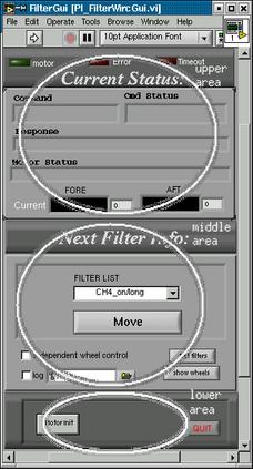
Motor init: Initializes both
filter wheels. This action needs to be performed at least the first time
you turn on the motor controller box. When you open the Plug-In, it will
try to communicate with the motor controller box. If it fails, it will
write the error messages in the status area. When
you press this button it performs the following actions:
a) Configure the serial line
b) Configure the two motor controller cards on the remote (Primary
focus) motor controller box (PIC-STEP)
c) Send both wheel to the home position. After each position has found
its home switch, it is sent automatically to the first valid position.
If for some reason you need to turn off the software, or close the
PI, the next time you open it it will again try to communicate with the
motor control box; if it was previously initialized it will receive the
right status and it will not be necessary to reinitialize
QUIT: quits the PI
Command: this are will show the actual serial command
sent to the motor controller box
Cmd Status: status of the command sent (like "waiting
response", or "OK", etc.)
Response: actual response got from the motor controller
box
Motor Status: status of the motor controller box according
to the last response to the "status" command (sent automatically) or to
the last issued command. This will be like "moving", etc.